Are you struggling to figure out if the electronic components on your circuit board are working properly? Testing these tiny parts might seem tricky, but with the right steps, you can quickly find out what’s good and what needs fixing.
Imagine saving hours of frustration by spotting faulty components early. You’ll discover simple, clear methods to test electronic components right on your board. Keep reading, and you’ll gain the confidence to troubleshoot like a pro, avoiding costly mistakes and getting your projects back on track faster than you thought possible.
Essential Tools
Testing electronic components on board requires the right set of tools to ensure accurate readings and effective troubleshooting. Without essential equipment, you risk damaging sensitive parts or misdiagnosing issues. Let’s break down the must-have tools that will empower you to test confidently and efficiently.
Multimeter Use
The multimeter is your most versatile tool for checking voltage, current, and resistance. You can quickly identify if a component is live or if a circuit is complete. When I first started, I underestimated the multimeter’s value until it helped me spot a tiny short that was causing a whole board to fail.
Using a multimeter, you can:
- Measure DC and AC voltages
- Test continuity to find broken connections
- Check resistor values directly on the board
Do you know how to set your multimeter to the right mode before testing? Picking the wrong setting can lead to false readings or even damage the device.
Oscilloscope Basics
An oscilloscope helps you visualize how signals behave over time, which is impossible with a multimeter alone. It’s essential for diagnosing timing issues or noise problems in circuits. I remember using an oscilloscope to catch a noisy clock signal that was causing erratic device behavior—something a multimeter never showed.
Key oscilloscope features to use include:
- Triggering to capture specific signal events
- Adjusting time base for detailed waveform analysis
- Using probes carefully to avoid loading the circuit
Are you familiar with how to connect the oscilloscope probes without affecting the circuit’s normal operation?
Soldering Equipment
Reliable soldering tools are critical for repairing or replacing components during testing. A good soldering iron with temperature control prevents overheating and damage to the board. Early in my work, I damaged a PCB by using a cheap iron that didn’t maintain steady heat—don’t let that happen to you.
Essentials to have include:
- Temperature-controlled soldering iron
- Quality solder wire with flux core
- Desoldering pump or wick for removing solder
Have you ever struggled with cold joints or lifted pads because of poor soldering tools? Using the right equipment makes your repairs cleaner and more reliable.
Identifying Components
Identifying electronic components on a circuit board is the first step in testing. Recognizing each part helps you understand its role and how to test it correctly. Components vary in shape, size, and markings. Knowing these differences makes troubleshooting easier.
Resistors And Capacitors
Resistors usually have colored bands showing their resistance value. Capacitors come in many types, such as ceramic, electrolytic, and film. Ceramic capacitors are small and disk-shaped. Electrolytic capacitors are cylindrical and have polarity marks. Checking the markings helps you select the right test method. Both resistors and capacitors affect current and voltage in circuits.
Diodes And Transistors
Diodes allow current to flow in one direction only. They often have a stripe marking the cathode side. Transistors have three legs and control current flow. They come in two types: NPN and PNP. Identifying the type helps decide which testing tool to use. These components are key for switching and amplifying signals.
Integrated Circuits
Integrated circuits (ICs) contain many components inside one package. They come in shapes like rectangles or squares with multiple pins. Pin numbers and part codes are printed on the surface. Knowing the IC type guides your test approach. Testing ICs requires careful handling to avoid damage.
Safety Precautions
Testing electronic components on board demands more than just the right tools and skills—it requires strict attention to safety. Ignoring safety precautions can damage sensitive parts or even cause personal injury. Understanding and applying key safety measures helps you protect both your components and yourself during the testing process.
Handling Static Sensitive Parts
Static electricity can silently destroy delicate components like MOSFETs and ICs. Always ground yourself before touching any static-sensitive parts. Using an anti-static wrist strap connected to a grounded surface is a simple yet effective way to avoid electrostatic discharge (ESD).
Keep your workspace free from materials that generate static, such as plastic or synthetic fabrics. Have you ever lost a component’s function with no visible damage? It’s often silent static shocks at work. Treat each sensitive part like it’s a glass sculpture—handle with care and grounded hands.
Proper Use Of Insulation
Insulation is your barrier against accidental shorts and electric shocks. Use insulated tools whenever possible to avoid direct contact with live circuits. Double-check that your test probes have intact insulation; worn tips can cause dangerous shorts or false readings.
Never touch exposed wires or terminals without verifying the circuit is powered down. If you must test a live board, stay alert and use equipment rated for the voltage you’re working with. How often do you inspect your tools for damage? A quick check can prevent costly mistakes.
Emergency Procedures
Knowing what to do in an emergency can save lives and equipment. Keep a fire extinguisher rated for electrical fires nearby, and know how to use it. In case of electric shock, disconnect the power immediately—never touch a shocked person if they are still in contact with the power source.
Have a clear plan for emergencies and communicate it with anyone working nearby. Quick access to first aid kits and emergency contact numbers makes a big difference. What’s your go-to action if something goes wrong during testing? Preparing in advance reduces panic and damage.
Testing Resistors
Testing resistors on a circuit board is a crucial skill that helps you ensure your electronic device functions correctly. Resistors control current flow, so a faulty one can cause significant issues. By testing resistors directly on the board, you save time and avoid unnecessary component removal.
Measuring Resistance
To measure resistance, you need a digital multimeter set to the resistance (ohm) mode. Place the probes on each end of the resistor while the board is powered off to avoid damage or inaccurate readings.
Look for the reading on the display and compare it to the resistor’s color code or the value printed on the schematic. A small difference is normal due to tolerance, but a large deviation suggests a problem.
If the resistor is part of a network or connected to other components, readings might be affected. In such cases, testing with the resistor removed or desoldered is more accurate. Have you ever noticed unexpected readings because of nearby components?
Identifying Faulty Resistors
Faulty resistors often show very high or infinite resistance, indicating an open circuit, or zero resistance, meaning a short circuit. These conditions disrupt the intended current flow and can damage other parts.
Visual inspection can also help spot issues. Look for burn marks, discoloration, or cracking on the resistor body, which often signal overheating or failure.
Sometimes, a resistor may pass the resistance test but still fail under load due to changes in its characteristics. If your circuit behaves oddly despite good resistance readings, consider swapping the resistor with a known good one to test functionality.
Testing Capacitors
Testing capacitors on a circuit board is key to finding faults. Capacitors store and release electrical energy. Faulty capacitors cause device malfunctions or failures. Simple tests reveal if a capacitor works well or needs replacement.
Capacitance Measurement
Use a digital multimeter with a capacitance setting. Remove power from the circuit before testing. Place the meter leads on the capacitor terminals. The meter shows the capacitance value in microfarads (µF). Compare this value to the capacitor’s rating. A large difference means the capacitor may be bad.
Some meters require the capacitor to be removed. Others can test in-circuit if no parallel components interfere. Always discharge the capacitor before measuring to avoid damage.
Detecting Leaks Or Shorts
Check for leakage current that wastes power and heats the capacitor. Use an insulation resistance tester or a multimeter set to resistance mode. A healthy capacitor shows very high resistance or no current flow. Low resistance or a beep sound indicates a leak or short circuit.
Visual inspection helps too. Look for bulging, cracks, or corrosion on the capacitor body. These signs mean the capacitor is likely damaged and should be replaced promptly.

Credit: www.viasion.com
Testing Diodes
Testing diodes on a circuit board is essential to check their health and function. Diodes control the direction of electrical flow. They allow current to pass in one direction and block it in the opposite direction. Checking diodes helps avoid circuit failure and ensures smooth operation.
Forward And Reverse Bias
Testing a diode requires applying voltage in two ways: forward bias and reverse bias.
- Forward Bias:Connect the positive lead of the multimeter to the diode’s anode and the negative lead to the cathode. The diode should allow current to pass, showing a low resistance or a voltage drop of about 0.6 to 0.7 volts for silicon diodes.
- Reverse Bias:Reverse the leads, connecting the positive lead to the cathode and the negative to the anode. The diode should block current, showing a very high resistance or no reading at all.
These two tests confirm if the diode works correctly. A good diode passes current in forward bias and blocks it in reverse bias.
Identifying Broken Diodes
Broken diodes show abnormal readings in either test. Common signs include:
- Low resistance in both directions, indicating a short circuit.
- High resistance or no reading in both directions, indicating an open circuit.
- A voltage drop far from the normal range in forward bias.
Use a digital multimeter with a diode test mode for accurate results. Replace diodes that fail these tests to keep the circuit safe and functional.
Testing Transistors
Testing transistors on the board helps find faults quickly. Transistors control current flow and act as switches or amplifiers. Checking them ensures the circuit works well. Use simple tools like a multimeter to test transistors without removing them. Focus on two main checks: junctions and gain. These checks reveal if the transistor is damaged or working fine.
Checking Junctions
Transistors have two junctions like diodes. Use the multimeter in diode mode for this test. Place the positive lead on the base and the negative on the collector or emitter.
- A good transistor shows a voltage drop of about 0.6 to 0.7 volts.
- Reverse the leads; it should show no conduction or open circuit.
- If both directions show conduction or no reading, the transistor is faulty.
Test both junctions: base to collector and base to emitter. Check all leads carefully to avoid wrong results. This method quickly spots shorts and opens inside the transistor.
Measuring Gain
Gain shows how well the transistor amplifies current. Use the multimeter’s hFE or gain mode if available. Connect the transistor legs to the multimeter socket according to the type (NPN or PNP).
The meter gives a number called hFE or beta. This number tells how much the transistor amplifies current. Compare this number with the transistor’s datasheet. A much lower or zero gain means the transistor may be bad.
This test helps confirm the transistor’s strength in the circuit without removing it. It saves time and avoids damage during repair.

Credit: www.fcpcba.com
Testing Integrated Circuits
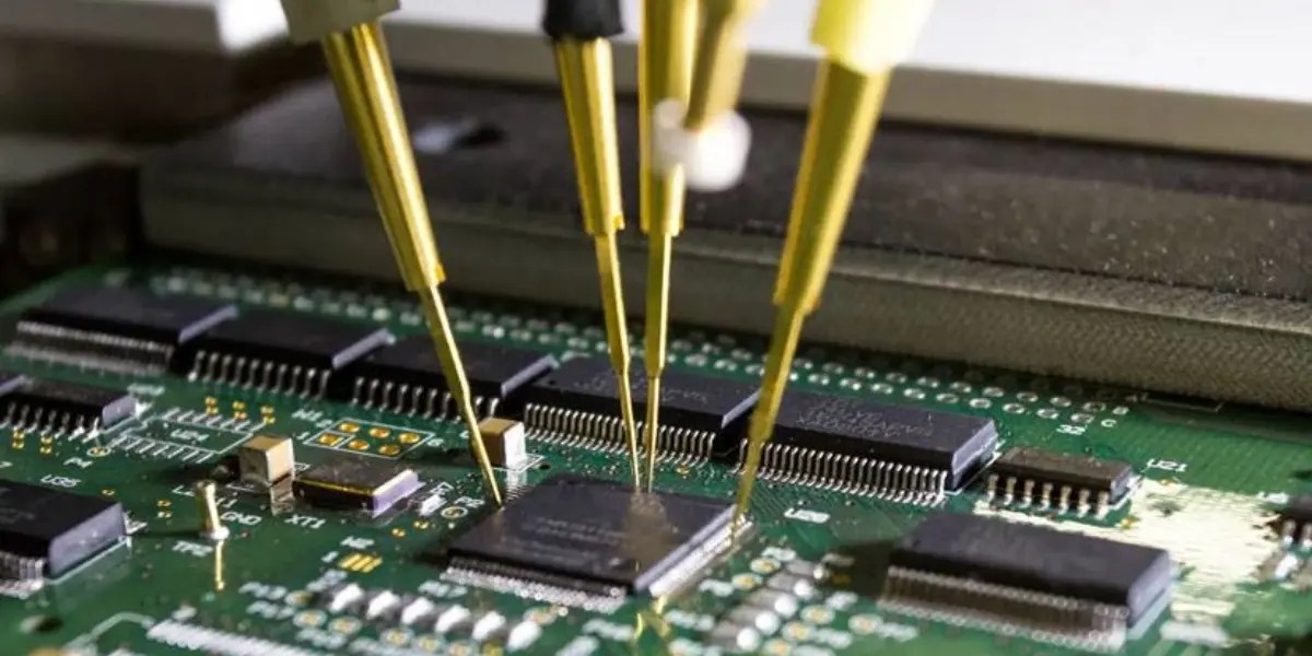
Testing integrated circuits (ICs) on a circuit board is a key step in troubleshooting and ensuring device reliability. These tiny chips perform complex tasks and need precise checking. A careful approach helps find faults without damaging the IC or the board.
Start by understanding the IC’s layout and role within the circuit. Use simple tools like a multimeter or logic probe to verify electrical connections and signal flow. Testing ICs on board saves time and avoids unnecessary replacements.
Pin Configuration
Know the pin layout before testing. Check the datasheet for the exact pin arrangement. Pin functions include power, ground, input, and output.
- Identify the power and ground pins to ensure proper voltage supply.
- Mark input and output pins to track signals during testing.
- Use a multimeter to check for shorts or open pins.
Correct pin identification prevents errors and potential damage during tests.
Functionality Tests
Test the IC’s operation by measuring its output response to known inputs.
- Apply power and observe if the IC heats up unusually.
- Use a logic probe or oscilloscope to check output signals.
- Compare output readings with expected values from the datasheet.
- Test input pins by applying signals and monitor output changes.
Functionality tests verify the IC performs its intended tasks on the board.
Troubleshooting Techniques
Troubleshooting electronic components on a board can feel like solving a puzzle. You need to identify the fault without damaging the board or wasting time. Using clear techniques helps you quickly pinpoint issues and fix them effectively.
Common Issues
Most problems arise from simple causes like loose connections, damaged components, or soldering faults. You might encounter:
- Broken traces or cracked solder joints
- Short circuits between pins or tracks
- Components that have overheated or failed
- Incorrect component placement or orientation
Spotting these common issues early saves hours of unnecessary testing. Have you ever spent more time hunting a missing wire than fixing the actual problem?
Signal Tracing
Signal tracing is a powerful way to track the flow of current or data through your circuit. Using a multimeter or oscilloscope, follow the signal path step-by-step from input to output.
- Start at the power source and check voltage levels at key points
- Look for unexpected drops or interruptions along the circuit
- Compare signals to the expected values from your schematic
By observing where the signal stops or changes, you can zero in on the faulty component or connection. Have you tried tracing signals to find hidden shorts or opens? It often reveals problems that visual inspection misses.
Credit: www.agsdevices.com
Using Simulation Software
Using simulation software is a smart way to test electronic components on a board without physical tools. This method allows you to model circuits and see how components behave under different conditions. It saves time and reduces errors in the design process.
Simulation software helps you predict problems before building the actual board. You can check voltage, current, and signal flow easily. It also supports learning and experimentation, especially for beginners in electronics.
Benefits Of Simulation
- Speeds up testing by avoiding physical setup.
- Reduces risk of damaging components during trials.
- Allows testing of complex circuits with many parts.
- Provides detailed analysis and visualization tools.
- Helps understand circuit behavior under different scenarios.
- Saves money on expensive testing equipment.
- Supports easy changes and quick retesting.
Popular Software Options
| Software | Description | Ideal For |
|---|---|---|
| LTspice | Free, fast, and widely used for analog circuits. | Hobbyists and professionals |
| Multisim | User-friendly, with a large component library. | Education and design engineers |
| Proteus | Combines circuit simulation with microcontroller testing. | Embedded system developers |
| Altium Designer | Advanced tool for PCB design and simulation. | Professional designers and engineers |
Frequently Asked Questions
How Do I Test Resistors On A Circuit Board?
To test resistors, use a multimeter set to the resistance mode. Place probes on resistor leads. Compare readings with resistor values to check functionality.
What Is The Best Way To Test Capacitors On Board?
Use a capacitance meter or multimeter with capacitance setting. Disconnect one capacitor lead and measure. Ensure values match the capacitor rating for accuracy.
Can I Test Diodes Without Removing Them?
Yes, use the diode test mode on a multimeter. Place probes on diode terminals. A forward voltage drop indicates a healthy diode.
How To Test Transistors Directly On The Pcb?
Test transistors using a multimeter in diode mode. Check base-emitter and base-collector junctions for proper forward voltage drop. Faulty junctions indicate transistor issues.
Conclusion
Testing electronic components on board helps find faults fast. Use a multimeter or oscilloscope to check connections. Always follow safety steps to avoid damage or injury. Regular testing keeps your circuits working well and saves time. Practice these simple methods to build confidence and skill.
Keep learning and stay patient during each test. Small checks prevent bigger problems later. Trust your tools and keep your work steady. Testing parts is key to good electronic repairs.
Leave a Reply