Are you struggling to figure out if your electronic components are working properly? Knowing how to check electronic components can save you time, money, and frustration.
Whether you’re fixing a gadget or building a project, understanding simple testing methods puts you in control. You’ll discover easy steps to test your parts quickly and accurately. By the end, you’ll feel confident handling your electronics like a pro.
Keep reading to unlock the secrets that make troubleshooting a breeze!
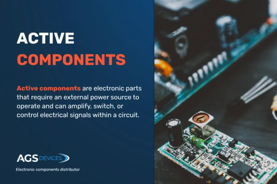
Credit: www.agsdevices.com
Types Of Electronic Components
Understanding the different types of electronic components is key to effectively checking and troubleshooting them. Each type serves a unique role in electronic circuits, and knowing their characteristics helps you identify potential issues quickly. Let’s break down some of the most common components you’ll encounter.
Resistors And Capacitors
Resistors control the flow of electric current by providing resistance. You can think of them as traffic controllers that manage how much current passes through a circuit.
Capacitors store and release electrical energy, acting like small energy reservoirs. They help stabilize voltage and filter out noise.
- Resistors come in fixed and variable types, with values measured in ohms (Ω).
- Capacitors vary by material and capacity, measured in farads (F), often microfarads (µF) or picofarads (pF).
When checking these components, you often use a multimeter to measure resistance or capacitance. Have you ever noticed a circuit behaving erratically because a capacitor was failing? That’s a clear sign these parts matter a lot.
Diodes And Transistors
Diodes allow current to flow in only one direction, protecting circuits from reverse voltage. They are essential in converting AC to DC current.
Transistors act as switches or amplifiers, controlling large currents with small input signals. Their role is crucial in almost every electronic device.
- Diodes are identified by their forward voltage drop, usually around 0.7V for silicon types.
- Transistors come in bipolar junction (BJT) and field-effect (FET) varieties, each with different testing methods.
Have you tried using a multimeter’s diode test mode? It’s a simple way to check if diodes and transistors are functioning properly.
Integrated Circuits
Integrated Circuits (ICs) combine many components like transistors, resistors, and capacitors into a single chip. They perform complex tasks in a compact form.
ICs vary widely, from simple logic gates to microcontrollers. Testing them often requires more than just a multimeter; sometimes you need an oscilloscope or specialized tester.
Ever struggled to find a fault inside an IC? It can be tricky, but understanding the IC’s datasheet and pin configuration gives you a huge advantage.

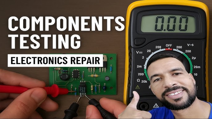
Credit: www.youtube.com
Tools For Testing Components
Testing electronic components requires the right tools for accurate results. Various devices help check if parts work correctly or need replacement. Using proper instruments saves time and prevents damage to circuits. Here are the main tools used to test electronic components.
Multimeter Basics
A multimeter measures voltage, current, and resistance in circuits. It helps check batteries, resistors, diodes, and more. Most multimeters have a digital display for easy reading. Set the dial to the correct mode before testing. Touch the probes to the component leads carefully. A good multimeter shows if a part is open, shorted, or functioning.
Oscilloscope Usage
An oscilloscope shows electrical signals as waveforms on a screen. It helps observe voltage changes over time. This tool is useful for checking complex parts like transistors and integrated circuits. Connect the probes to test points on the circuit board. Watch the waveform shape and frequency to find issues. Oscilloscopes reveal problems that simple meters cannot detect.
Component Testers
Component testers check specific parts like transistors, capacitors, and diodes. They provide detailed information on component health and values. These testers often display results automatically, making them user-friendly. Small, portable models work well for quick checks. Using a component tester ensures accurate diagnosis without guesswork.
Testing Resistors And Capacitors
Testing resistors and capacitors requires a multimeter to measure resistance and capacitance values. Checking these parts helps ensure they work correctly in circuits. Simple tests can identify damaged or faulty components quickly.
Testing resistors and capacitors is crucial for electronic projects. These components play vital roles in circuits. Ensuring they function properly saves time and resources. Testing them requires tools like a multimeter. Understanding their behavior helps diagnose issues in electronics. Below are the steps to test resistors and capacitors.Measuring Resistance
Use a digital multimeter to measure resistance. Set the multimeter to the resistance setting. Connect the probes to the resistor’s leads. Read the displayed value on the screen. Ensure the resistor is not connected to a circuit. Compare the measured value to the expected resistance. If it matches, the resistor is good.Checking Capacitance
To check a capacitor, use a multimeter with capacitance mode. First, discharge the capacitor safely. Set the multimeter to measure capacitance. Connect the probes to the capacitor’s terminals. Observe the reading on the multimeter. Compare it with the capacitor’s rated value. A significant difference indicates a faulty capacitor.Identifying Faulty Components
Faulty components disrupt circuits. Check resistors for burned or damaged appearances. Inspect capacitors for bulging or leaking. Replace any components with physical damage. Use a multimeter to confirm the fault. Testing ensures components are reliable. Keep your circuit functional and efficient.
Credit: www.viasion.com
Testing Diodes And Transistors
Testing diodes and transistors is essential for verifying their functionality. These components control the flow of current in electronic circuits. Faulty diodes or transistors can cause devices to malfunction or fail.
Simple tests can identify if these parts work correctly. Using a multimeter helps measure their electrical properties. Understanding how to test these components saves time and money in repairs.
Forward And Reverse Bias Testing
Diodes allow current to flow in one direction only. Forward bias means the positive terminal connects to the diode’s anode. Reverse bias connects the positive terminal to the cathode.
In forward bias, a good diode shows a low voltage drop, usually around 0.6 to 0.7 volts. In reverse bias, it shows no current flow or a very high resistance. A diode that conducts in both directions is faulty.
Using The Diode Test Mode
Most digital multimeters have a diode test mode. This mode applies a small voltage to the diode and measures voltage drop. Connect the red probe to the anode and black to the cathode.
The meter displays the forward voltage drop if the diode is good. Reverse the probes to check the reverse bias. A high or infinite reading means the diode blocks current correctly in reverse.
Transistor Gain Measurement
Transistors amplify current, and their gain is a key parameter. Gain is the ratio of output current to input current. Use a multimeter with a transistor test function for this measurement.
Insert the transistor leads into the correct slots on the tester. The meter displays the gain, labeled as hFE or Beta. Low or zero gain indicates a damaged transistor. Testing gain helps choose the right transistor for your circuit.
Testing Integrated Circuits
Testing integrated circuits (ICs) is essential to ensure their proper function in electronic devices. Faulty ICs can cause device failures or erratic behavior. Detecting problems early saves time and money during repairs and builds confidence in device performance.
Different methods help check ICs, from simple visual checks to advanced testing tools. Each method reveals unique information about the IC’s condition. Understanding these techniques improves troubleshooting skills and helps maintain reliable electronics.
Visual Inspection Techniques
Start by examining the IC closely under good light. Look for cracks, burn marks, or corrosion on the chip surface. Check the pins for bending, breakage, or dirt. Dirty or damaged pins can cause poor connections.
Use a magnifying glass or microscope for a detailed view. Inspect the solder joints for cold solder or cracks. Uneven solder or gaps may lead to faulty circuits. Look for discoloration, which may signal overheating.
Functional Testing Methods
Functional tests verify if the IC works as intended. Use a simple circuit to power the IC and measure output signals. Compare the results with the IC datasheet specifications. Check voltage levels, signal timing, and response to inputs.
Testing ICs in the actual circuit helps find faults caused by other components. Use a multimeter to measure voltage and current at the IC pins. Oscilloscopes help see signal waveforms and timing issues. Functional tests highlight ICs that fail to perform correctly.
Using Ic Testers
IC testers provide a fast and reliable way to check many IC types. Insert the IC into the tester socket and run the test program. The tester checks the IC’s logic functions and pin connections.
Testers display pass or fail results, often with detailed error codes. They save time compared to manual testing. Some testers support a wide range of IC packages and types. Using an IC tester reduces guesswork and improves accuracy.
Common Testing Errors To Avoid
Testing electronic components requires care and attention to avoid common mistakes. Errors during testing can lead to wrong conclusions and wasted time. Knowing what to avoid helps achieve accurate and reliable results.
Incorrect Meter Settings
Using the wrong setting on your meter is a frequent error. Each component needs a specific test mode, such as resistance, continuity, or diode check. Testing a diode with the resistance mode gives false readings. Always double-check your meter’s settings before testing. This simple step prevents confusion and incorrect results.
Ignoring Component Datasheets
Datasheets provide vital information about a component’s limits and characteristics. Skipping this step can cause misinterpretation of test results. For example, some capacitors have a specific voltage rating you must consider. Without this knowledge, you might think a component is faulty when it is not. Always review datasheets to understand what test values to expect.
Misinterpreting Test Results
Reading test results without context leads to mistakes. A slightly higher or lower reading does not always mean the component is defective. Some parts have tolerances and normal variations. Comparing results to the datasheet helps you judge if a component is working properly. Take time to analyze the numbers carefully before making decisions.
Tips For Accurate Component Testing
Accurate testing of electronic components ensures reliability and prevents costly errors. Following specific tips can improve test results and protect both the tester and the components. Testing with care leads to better performance and longer component life.
Proper Calibration Of Equipment
Test tools must be calibrated regularly. Calibration checks ensure measurements are accurate and trustworthy. Use standard reference materials or calibration kits. Keep calibration certificates for records. Avoid using uncalibrated or damaged equipment. Accurate tools provide precise readings and avoid false results.
Safe Handling Practices
Handle components gently to avoid damage. Use anti-static wrist straps to prevent static discharge. Work on clean, dry surfaces free of dust. Store parts in labeled containers to avoid mix-ups. Avoid touching pins or leads directly with fingers. Proper handling keeps components intact and testing safe.
Record Keeping For Consistency
Maintain detailed test records for every component. Note date, equipment used, test settings, and results. Use a digital or paper logbook for easy access. Compare current results with past tests to detect changes. Good records help track component quality and improve testing processes.
Frequently Asked Questions
How Do I Test A Resistor With A Multimeter?
To test a resistor, set the multimeter to the resistance mode (ohms). Place probes on each resistor lead and read the value. Compare it to the resistor’s rated value to check if it’s within tolerance.
What Is The Best Way To Check A Capacitor?
Use a capacitance meter or multimeter with a capacitance function. Discharge the capacitor first, then measure its capacitance and compare it to the rated value for accuracy.
How Can I Identify A Faulty Diode?
Set the multimeter to diode mode. Place the probes on the diode leads; a good diode shows low resistance in one direction and high in the other.
What Tools Are Essential For Checking Electronic Components?
A digital multimeter, capacitance meter, and an LCR meter are essential. These tools measure resistance, capacitance, inductance, and continuity effectively.
Conclusion
Checking electronic components is simple with the right steps. Use basic tools like a multimeter to test parts clearly. Always follow safety rules to avoid damage or injury. Practice makes it easier to spot faulty components. This skill helps fix devices and build electronics confidently.
Keep learning and testing to improve your knowledge daily. Small efforts lead to better results over time. Stay patient and curious during each check. Your electronic projects will benefit from careful inspection.
Leave a Reply