Are you struggling to figure out if your electronic components are working properly? Testing multiple components can feel overwhelming, especially if you’re not sure where to start.
But what if you could quickly and confidently check each part without stress or confusion? In this guide, you’ll discover simple, effective ways to test various electronic components step-by-step. By the end, you’ll save time, avoid costly mistakes, and keep your projects running smoothly.
Ready to unlock the secrets to easy and accurate testing? Let’s dive in.
Essential Tools For Testing
Testing electronic components requires the right tools. These tools help ensure accuracy and efficiency. With the correct equipment, diagnosing issues becomes easier. Let’s explore some essential tools for testing electronic components.
Multimeters And Their Functions
Multimeters are versatile tools. They measure voltage, current, and resistance. Use them to check continuity in circuits. They help identify faulty components. Digital multimeters are most common. They provide precise readings. Analog versions are available too. They’re useful for visualizing trends. Multimeters are essential for basic testing tasks.
Oscilloscopes In Component Testing
Oscilloscopes display voltage changes over time. They’re vital for analyzing waveforms. They help in identifying signal problems. Use them to test oscillators and signal generators. Oscilloscopes can measure frequency and amplitude. This makes them crucial for complex tasks. They provide a graphical view, unlike multimeters. Oscilloscopes are invaluable for detailed analysis.
Specialized Testers
Specialized testers focus on specific components. They test transistors, capacitors, and diodes. These testers simplify the testing process. They provide quick results with minimal setup. Some testers identify component values and faults. They’re user-friendly, even for beginners. Specialized testers enhance efficiency in testing multiple components. They’re a great addition to any toolkit.

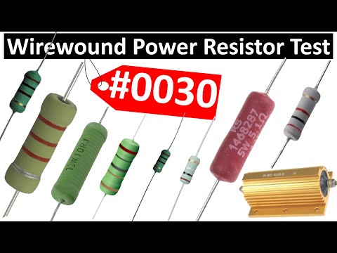
Credit: www.youtube.com
Testing Resistors And Capacitors
Testing resistors and capacitors is essential for verifying circuit functionality. These components often affect overall performance. Faulty parts can cause devices to malfunction or fail. Simple tests can save time and money by identifying problems early. Basic tools like multimeters help measure resistance and capacitance quickly. Understanding these tests improves troubleshooting skills.
Measuring Resistance Accurately
Use a digital multimeter to measure resistance. Set the meter to the resistance (ohm) mode.
Follow these steps:
- Disconnect the resistor from the circuit.
- Touch the probes to each resistor lead.
- Read the resistance value on the display.
Compare the reading to the resistor’s color code or datasheet value. A small difference is normal. Large deviation indicates a damaged resistor. Avoid touching the metal probe tips to prevent false readings.
Checking Capacitance Quickly
A multimeter with capacitance mode measures capacitors fast. For accurate results, discharge the capacitor first.
- Disconnect the capacitor from the circuit.
- Press the probes on the capacitor leads.
- Read the capacitance value on the screen.
Values close to the capacitor rating show it works well. A reading of zero or very high means a faulty capacitor. Testing helps spot leaks or shorts before full failure.
Testing Diodes And Transistors
Testing diodes and transistors is a key task in electronics troubleshooting. These components control current flow and switching in circuits. Faulty diodes or transistors can cause device failure or poor performance. Knowing how to test them helps identify issues quickly. It also saves time and prevents replacing parts unnecessarily.
Simple tools like a multimeter can check diode and transistor health. Understanding their basic properties allows accurate testing. This section explains how to test diodes and transistors step-by-step. Clear instructions make it easy even for beginners.
Diode Forward And Reverse Bias Tests
Diodes allow current to flow in one direction only. Testing involves checking this property using a multimeter’s diode mode.
- Set the multimeter to diode test mode.
- Connect the positive lead to the diode’s anode and the negative to the cathode.
- The meter should show a voltage drop around 0.6 to 0.7 volts for silicon diodes.
- Reverse the leads; the meter should read “OL” or no conduction.
This confirms the diode conducts in one direction and blocks in the other. If it reads zero volts or no reading both ways, the diode is faulty.
Transistor Junction Testing
Transistors have two junctions similar to diodes. Checking these junctions helps test transistor condition.
- Identify transistor pins: base, collector, and emitter.
- Set the multimeter to diode test mode.
- Test base to emitter and base to collector junctions like diodes.
- Forward bias (positive lead to base) should show 0.6 to 0.7 volts.
- Reverse bias shows no conduction.
- Collector to emitter should show no conduction in either direction.
If any junction fails these tests, the transistor may be damaged. This simple check saves time before full circuit testing.

Credit: m.youtube.com
Testing Integrated Circuits
Testing integrated circuits (ICs) is essential for verifying their functionality before use. ICs can have many pins and complex internal structures. Simple testing methods help identify faulty chips quickly. Proper testing ensures reliable circuit performance and saves troubleshooting time.
Basic Ic Functionality Checks
Start by checking the datasheet for pin configuration and voltage levels. Use a multimeter to test power supply pins for correct voltage. Measure resistance between input and output pins to spot shorts or open circuits.
Use a logic probe or oscilloscope to check signal levels on logic ICs. Apply known input signals and observe the output response. Compare the output with expected values from the datasheet.
- Check power supply and ground pins.
- Test input signals for correct voltage.
- Observe output signals for proper operation.
- Look for shorts or open circuits between pins.
Using Test Sockets And Adapters
Test sockets simplify the process of inserting and removing ICs during testing. They protect the IC pins from damage. Adapters allow testing ICs with different pin layouts on standard test equipment.
Use test sockets to hold the IC firmly and ensure good contact. Some sockets have zero insertion force, preventing pin bending. Adapters convert IC pin formats for compatibility with testers.
- Choose sockets matching the IC package type.
- Use zero insertion force sockets for delicate ICs.
- Adapters help test surface mount ICs with through-hole equipment.
- Ensure secure connections for accurate test results.
Quick Testing Techniques
Quick testing techniques are essential when you need to check multiple electronic components efficiently. These methods save time and reduce errors, especially when dealing with numerous parts in a project or repair job. You can maintain accuracy without spending hours on each component.
Using Test Clips And Probes
Test clips and probes allow you to connect to components without soldering or permanent attachment. They help you quickly measure voltage, resistance, or continuity on tiny pins and leads.
If you’ve ever struggled holding tiny wires in place while testing, test clips can be a game-changer. They free up your hands and provide stable contact, which is crucial for consistent readings.
- Choose clips that fit the component size — IC clips for integrated circuits, grabber probes for small leads.
- Make sure your multimeter or testing device is compatible with the clip or probe.
- Use clips on live circuits cautiously to avoid shorts or damage.
Have you noticed how much easier it is to test components mounted on a board with clips compared to bare leads? This technique is especially useful during troubleshooting.
Batch Testing Multiple Components
Testing several components at once speeds up your workflow, but it requires planning. Group similar components, like resistors or capacitors, with close values to check them in batches.
You can set up a simple test rig with a breadboard or a custom fixture that holds components in place. Connect your testing device to this setup and take multiple readings quickly.
- Label components clearly to avoid mixing results.
- Use a multimeter with a hold function to capture readings without rushing.
- For semiconductors, use a dedicated tester that can handle multiple diodes or transistors simultaneously.
Think about how much time you waste testing components one by one. Could a batch approach improve your efficiency without sacrificing accuracy? Trying this might change your entire testing routine.
Common Testing Mistakes
Testing multiple electronic components can be tricky, and common mistakes often lead to inaccurate results or even damage. Recognizing these pitfalls helps you save time and avoid frustration. Let’s look at some frequent errors and how you can steer clear of them.
Avoiding False Readings
False readings are a common headache when testing electronics. They can happen because of poor contact between your probe and the component leads or because the component isn’t isolated from the circuit. Always ensure your test leads touch firmly and cleanly on the exact points you want to measure.
Another source of false readings is testing components while they are still connected in a circuit. This can cause interference from other parts, leading to confusing or incorrect values. Try removing the component or isolate it from the circuit for accurate results.
Have you ever thought about how temperature affects your readings? Electronic parts behave differently when warm or cold. Testing components at room temperature usually gives the most reliable data, so avoid testing right after the device has been running for hours.
Handling Sensitive Components Safely
Some components, like MOSFETs and integrated circuits, are highly sensitive to static electricity. Simply touching their leads without proper grounding can damage them. Make sure you use a grounded wrist strap or anti-static mat to protect these parts while testing.
Another safety tip is to avoid applying excessive voltage or current during testing. Overloading a component can destroy it instantly. Use the correct settings on your multimeter or tester and double-check before turning the device on.
Have you noticed how easily some components slip from your fingers? Handling them carefully prevents physical damage and maintains their reliability. Use tweezers or small clamps, especially when dealing with tiny surface-mount devices.
Improving Accuracy In Results
Improving accuracy in testing multiple electronic components is key to reliable results. Small errors can lead to misdiagnosis of faults or wasted time troubleshooting. Paying attention to details like equipment calibration and environmental conditions can make a big difference in the quality of your measurements.
Calibration Of Testing Equipment
Regular calibration of your testing tools is essential. Over time, devices like multimeters and oscilloscopes may drift from their original settings, causing inaccuracies.
Set a schedule to calibrate your equipment using certified standards or reference devices. This ensures your readings match true values and reduces guesswork.
Have you ever blamed a component for failure only to find the tester was off? Proper calibration saves you from chasing phantom issues.
Environmental Factors To Consider
Environmental conditions can impact your testing results more than you might expect. Temperature, humidity, and electromagnetic interference all affect electronic measurements.
Try to test components in a stable environment. Avoid areas near heavy machinery or strong radio signals that could introduce noise in your readings.
- Keep the workspace clean and dry to prevent static buildup.
- Control room temperature to stay within device operating limits.
- Use shielding or grounding techniques to minimize interference.
Have you noticed fluctuations in your results without changing anything else? Environmental factors might be the hidden culprit.
Credit: www.pcbasic.com
Frequently Asked Questions
How Do I Test Multiple Electronic Components Efficiently?
Use a multimeter with a test kit to check components quickly. Test resistors, capacitors, and diodes in sequence. Label each component to avoid confusion. This method saves time and ensures accurate results.
What Tools Are Best For Testing Electronic Components?
A digital multimeter, LCR meter, and component tester are ideal. They measure resistance, capacitance, and transistor functionality. These tools help identify faulty components easily and precisely.
Can I Test Components Without Removing Them From The Circuit?
Yes, but results may be less accurate due to circuit interference. For best results, remove components when possible. Testing in-circuit is useful for quick checks or large assemblies.
How Do I Identify Faulty Electronic Components?
Look for unusual readings like open circuits or shorts using a multimeter. Compare measurements to standard values in datasheets. Physical signs like burns or cracks also indicate faults.
Conclusion
Testing multiple electronic components requires careful steps and patience. Start by organizing the parts and tools you need. Use a multimeter or tester to check each component’s function. Take your time and test one piece at a time. Keep notes of your results for easy reference.
This process helps you find faulty parts quickly. With practice, testing becomes faster and more accurate. Remember, safety first—always handle electronics carefully. Testing components correctly saves time and prevents bigger problems later. Simple steps lead to better repairs and stronger devices.
Leave a Reply