Have you ever stared at a small electronic part and wondered what it actually does? Identifying electronic components might seem tricky at first, but it’s easier than you think.
Knowing how to recognize resistors, capacitors, diodes, and other parts can save you time and frustration when fixing gadgets or building projects. You’ll discover simple tips and tricks to quickly identify the most common electronic components. By the end, you’ll feel confident handling these tiny pieces like a pro.
Ready to unlock the secrets behind those mysterious parts? Let’s dive in!

Credit: www.electronicsandyou.com
Common Electronic Components
Identifying electronic components involves checking their shapes, sizes, and markings. Reading labels and symbols helps recognize resistors, capacitors, and transistors easily. Using a simple guide or chart can make this process faster and clearer.
Identifying electronic components can be daunting if you’re new to electronics. However, knowing the common components can make your journey smoother. With a little practice, you’ll be able to spot these parts on a circuit board with ease. Understanding how each component looks and functions is crucial. You might even find yourself recalling that time you fixed your own device simply by recognizing these tiny yet significant parts. Here’s a closer look at some of the most common electronic components:Resistors
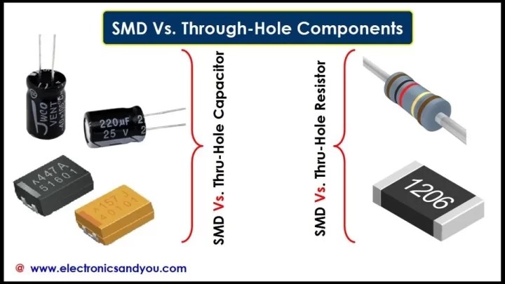
Resistors are like the brakes in your circuit. They limit the flow of electric current, protecting other components from damage. Look for small cylindrical components with colored bands; these colors indicate their resistance value.Capacitors
Capacitors store and release electrical energy, much like a battery. They can be identified by their two terminals and are usually marked with their capacitance value. You’ll often find them in shapes like a tiny can or disc.Inductors
Inductors are often in the form of coils and are used to store energy in a magnetic field. They can help filter signals or manage the flow of power in a circuit. Their appearance is similar to that of a resistor but without the color bands.Diodes
Diodes allow current to flow in one direction only, acting as a one-way gate. They are typically black with a silver stripe indicating the direction of current flow. Remember the time your gadget wouldn’t power up due to a faulty diode?Transistors
Transistors are the workhorses of electronics, used for switching or amplifying signals. They come in various shapes but usually have three legs. Spotting them might remind you of the small but mighty role they play in your devices.Integrated Circuits
Integrated circuits, or ICs, are complex components that can perform multiple functions. They are usually black with multiple legs or pins and can be thought of as mini-circuit boards. Their widespread use in electronics highlights their versatility. By familiarizing yourself with these components, you enhance your ability to troubleshoot and repair electronic devices. Isn’t it fascinating to think about how these small pieces create such significant impact in our technological world?
Credit: www.reddit.com
Component Markings And Codes
Understanding the markings and codes on electronic components is essential for anyone working with circuits. These tiny inscriptions tell you a lot about the component’s value, type, and specifications. Learning to read them helps you identify parts quickly without needing extra tools or datasheets.
Color Codes On Resistors
Resistors use color bands to indicate their resistance values. Each color corresponds to a number, and the sequence of bands reveals the value and tolerance.
For example, a resistor with bands colored red, violet, yellow, and gold means 27 (red=2, violet=7) followed by 10,000 (yellow multiplier), with a 5% tolerance (gold). You can use a simple chart or a smartphone app to decode these colors instantly.
Have you noticed how these color codes make identifying resistors in a mixed kit faster? It’s a handy skill that saves time during repairs or builds.
Capacitor Labels
Capacitors often have their values printed directly on the body in microfarads (µF), nanofarads (nF), or picofarads (pF). Sometimes, they use a three-digit code similar to resistors.
For example, a capacitor labeled “104” means 10 followed by 4 zeros in picofarads, or 100,000 pF (0.1 µF). Electrolytic capacitors also include polarity markings, which are crucial to avoid damage.
Pay close attention to these labels—mixing up capacitor values or polarity can cause circuit failure or even damage your device.
Transistor And Diode Markings
Transistors and diodes usually have short alphanumeric codes printed on them, like “2N2222” or “1N4148.” These codes identify the exact model and specifications.
You can look up these codes online or in component databases to find pin configurations and electrical characteristics. Some transistors also have a dot or a notch to indicate the emitter or cathode.
Ever tried replacing a transistor without checking its code? It often leads to confusion and non-working circuits. Make it a habit to verify these markings before soldering.
Ic Part Numbers
Integrated Circuits (ICs) carry detailed part numbers that can look complex but actually provide a lot of information. Numbers like “LM358” or “ATmega328” tell you the function and manufacturer.
These numbers are your key to finding datasheets, pin layouts, and application notes. Some ICs also have date codes and batch numbers, which help in quality control and troubleshooting.
Have you ever tried identifying an IC just by its shape? Without the part number, it’s almost impossible to know what it does or how to connect it properly.
Tools For Identification
Identifying electronic components requires the right tools to ensure accuracy. These tools help check component values and verify their function. Using proper equipment saves time and prevents errors.
Tools for identification vary from simple meters to detailed datasheets. Each tool plays a specific role in the process. Learning how to use them is essential for electronics work.
Multimeter Usage
A multimeter measures voltage, current, and resistance in components. It helps determine if a part works or is damaged. Using the resistance mode, you can check resistors and continuity. The diode test mode verifies diodes and transistors.
Hold the probes carefully on the component leads. Read the values displayed on the screen. Compare these values to expected ones to identify the component type.
Component Testers
Component testers are small devices that identify and test various parts. They often show component type and pin configuration on a screen. Plug the component into the tester socket to get instant results.
These testers work well for capacitors, transistors, diodes, and resistors. They provide quick and clear identification, especially for unknown parts.
Datasheets And Manufacturer Resources
Datasheets are detailed documents from manufacturers about components. They include specs like voltage ratings, pin layout, and physical dimensions. Search online using the component’s part number to find datasheets.
Manufacturer websites also offer manuals and application notes. These resources clarify component functions and uses. Always check datasheets to confirm component identity and details.
Practical Tips For Identification
Identifying electronic components accurately is essential for repairing or building circuits. Practical tips help you recognize components quickly and avoid costly mistakes. Let’s look at some effective ways to sharpen your identification skills.
Visual Inspection Techniques
Start by examining the component’s shape, size, and markings. Many components have printed codes or color bands that reveal their values and types.
Use a magnifying glass or a jeweler’s loupe to read tiny numbers or letters. Sometimes dirt or wear can obscure markings, so clean the component gently before inspecting.
Look for physical signs like burn marks or cracks that indicate damage. Have you ever misread a resistor’s color code and ended up troubleshooting for hours? Paying attention here saves time later.
Using Circuit Diagrams
Circuit diagrams are your roadmap to identifying components in a complex setup. They show symbols and labels that correspond to real parts on the board.
Match symbols in the diagram to the shapes and labels on your components. For example, a zigzag line represents a resistor, while a triangle with a line often shows a diode.
Double-check component values against the diagram to avoid swapping parts. Have you checked your circuit diagram before replacing a component and found a mismatch? It’s a simple step that prevents errors.
Handling And Safety Precautions
Always turn off power and unplug devices before you touch any electronic components. This protects both you and the parts from damage.
Wear an anti-static wrist strap when handling sensitive components like ICs or memory chips. Static electricity can ruin these parts without visible signs.
Use proper tools like tweezers or pliers to avoid bending or breaking tiny leads. Have you ever lost a crucial component because it slipped away? Good handling keeps your workspace organized and safe.
Common Mistakes To Avoid
Identifying electronic components might seem straightforward, but many beginners and even experienced hobbyists slip up on simple details. These mistakes can lead to circuit failures or damage to parts, costing you time and money. Avoiding common pitfalls helps you build confidence and get better results faster.
Misreading Color Codes
Resistors and some capacitors use color bands to show their values. Misinterpreting these colors is a frequent error, especially under poor lighting or when the bands are faded. Have you ever grabbed a resistor only to find your circuit didn’t behave as expected? Double-check the color code chart and use a multimeter to verify resistance before soldering.
Keep a printed or digital color code reference handy. Remember that the tolerance band (often gold or silver) is crucial—it tells you how much the actual value can vary. Skipping this detail can lead to incorrect assumptions about component performance.
Ignoring Polarity
Some components, like electrolytic capacitors, diodes, and LEDs, only work when placed the right way around. Ignoring polarity can cause components to fail immediately or degrade over time. Have you ever installed an LED that just wouldn’t light up? Check the markings carefully—usually a stripe or a flat side indicates the negative terminal.
Using a magnifying glass to read tiny polarity signs can save you headaches. If the datasheet is available, consult it for precise pin configuration. Trusting your eyes alone often isn’t enough.
Overlooking Component Ratings
Every component has limits on voltage, current, power, and temperature. Using parts beyond their ratings can cause overheating or permanent damage. Have you ever seen a resistor burn out or a capacitor bulge? These failures often result from ignoring rating specs.
Always check the datasheet before adding a component to your design. If your circuit demands 10V, don’t use a capacitor rated for 6.3V. Choose components with a safety margin to ensure reliability and longer life.

Credit: www.electronicsandyou.com
Advanced Identification Methods
Advanced identification methods help recognize electronic components beyond basic visual checks. These methods use tools and techniques to test and analyze parts in real circuits. They provide accurate details about component behavior and function.
Using these methods improves troubleshooting and repair skills. It also aids in understanding complex circuit designs. Learning these techniques is useful for hobbyists and professionals alike.
Using Oscilloscopes
Oscilloscopes display electronic signals as waveforms. They show voltage changes over time, revealing component behavior. This helps identify components by their signal patterns.
- Check signal shape to distinguish resistors, capacitors, and inductors.
- Measure frequency response to identify filters and oscillators.
- Detect faults like shorts or open circuits in components.
Oscilloscope probes connect to test points on a circuit. Observing live signals reveals how each part works under real conditions.
Soldering And Desoldering Tips
Careful soldering and desoldering let you remove components without damage. This is key for testing unknown parts or replacing faulty ones.
- Use a temperature-controlled soldering iron for precision.
- Apply flux to improve solder flow and reduce heat damage.
- Desolder with wick or a pump to cleanly remove old solder.
- Handle components gently to avoid breaking leads or boards.
Good soldering skills ensure components remain usable after removal. They also make reassembly easier and safer.
Reverse Engineering Circuits
Reverse engineering involves studying a circuit to identify its parts and layout. It uncovers component types and connections without original schematics.
- Trace circuit paths to map component relationships.
- Compare parts with datasheets to confirm specifications.
- Use continuity tests to check connections between components.
- Document findings to rebuild or repair the circuit confidently.
This method reveals hidden components and circuit functions. It enhances understanding of design and helps recreate or modify devices.
Frequently Asked Questions
How Do I Read Electronic Component Labels?
Electronic component labels often include alphanumeric codes. These codes indicate the component type, value, and tolerance. Consult datasheets for exact meanings. Learning standard codes helps identify resistors, capacitors, and semiconductors quickly and accurately.
What Tools Help Identify Electronic Components?
A multimeter is essential for measuring resistance, capacitance, and voltage. LCR meters provide precise inductance, capacitance, and resistance readings. Visual inspection with a magnifier and component datasheets also aid accurate identification.
How To Identify Resistors By Color Codes?
Resistors use colored bands to show resistance value and tolerance. Each color corresponds to a specific digit or multiplier. Learning the color code chart lets you decode resistance quickly without extra tools.
Can I Identify Components Without Datasheets?
Basic components like resistors and capacitors can be identified by color codes or markings. Complex parts need datasheets for pin configuration and specifications. Online databases and manufacturer websites are valuable resources.
Conclusion
Identifying electronic components is easier with practice and patience. Start by learning basic symbols and markings on parts. Use a multimeter to test resistors, capacitors, and diodes. Always check datasheets for detailed information. Small steps build your confidence and skills.
Soon, reading and understanding components will feel natural. Keep exploring and experimenting to improve your knowledge. This skill helps in fixing and building electronics safely. Stay curious and enjoy the process of discovery.
Leave a Reply