Have you ever wondered why electronic components come in different sizes and shapes? One key factor that affects how these parts fit together is something called “pitch.”
Understanding pitch can make a big difference when you’re working on circuits or choosing the right components for your project. You’ll discover exactly what pitch is, why it matters, and how it impacts your electronic designs. By the end, you’ll have a clear grasp of this simple yet important concept that can save you time, money, and frustration.
Keep reading to unlock the secret behind pitch in electronic components!
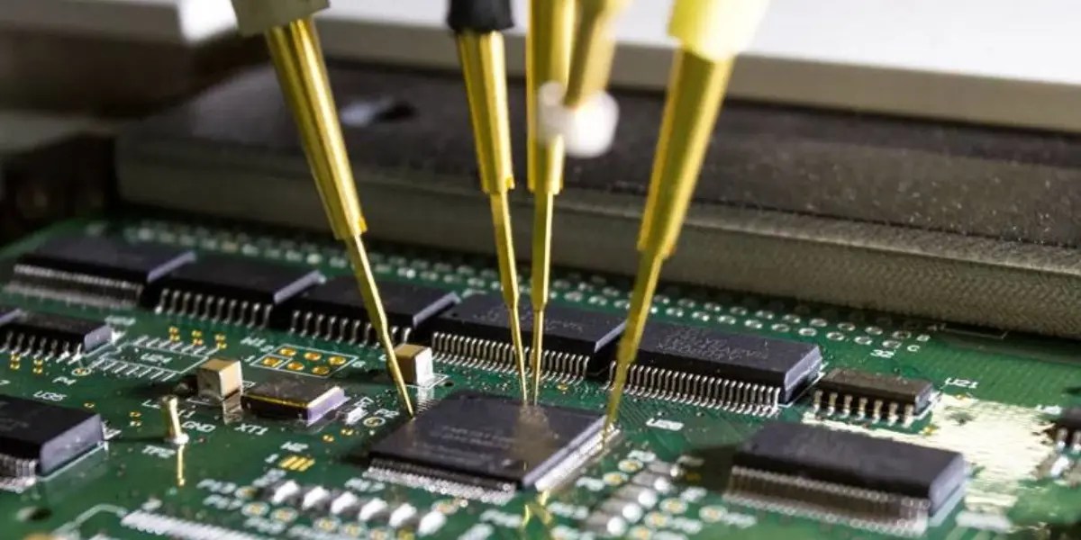
Pitch In Electronics
Pitch in electronics refers to the space between components. It is a crucial aspect in the design and functionality of electronic devices. Understanding pitch helps in creating efficient and reliable electronic systems.
Basic Concept
The pitch is the distance between two identical points on adjacent components. For instance, in a row of pins, it is the center-to-center distance. This measurement ensures components fit together properly on a circuit board.
Pitch is vital in the layout of printed circuit boards (PCBs). Proper pitch ensures all parts align and connect seamlessly. It prevents short circuits and mechanical stress.
Importance In Design
Correct pitch is essential for manufacturing precision. It affects how components are placed on a PCB. A mismatch in pitch can lead to assembly issues. Designers must consider pitch to ensure a smooth production process.
Pitch influences component compatibility. Devices with different pitches may not fit together. Ensuring the right pitch enhances device performance and longevity.
In summary, pitch impacts the design, assembly, and function of electronic components. It is a fundamental aspect that designers must carefully consider.
Credit: probots.co.in
Types Of Pitch
Understanding the different types of pitch is key to selecting the right electronic components for your project. Pitch refers to the spacing between pins or leads on components, and it affects how parts fit on a circuit board. Knowing the types helps you avoid compatibility issues and design errors.
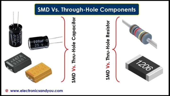
Lead Pitch
Lead pitch is the distance between the centers of adjacent leads or pins on a component. It’s critical for through-hole components like resistors and capacitors. If the lead pitch doesn’t match your PCB design, the component won’t fit properly, causing soldering problems.
For example, a common lead pitch for resistors is 2.54 mm (0.1 inch). When you buy components, always check this measurement against your board layout. Have you ever struggled with a component that just wouldn’t sit right? Lead pitch is often the culprit.
Grid Pitch
Grid pitch refers to the spacing in a grid pattern, often used for connectors and headers. This type of pitch ensures that multiple pins line up both horizontally and vertically. It helps maintain uniformity when placing components that connect several circuits.
Standard grid pitches are usually 2.54 mm or 1.27 mm. If you’re working with modular connectors, keeping track of grid pitch is essential. This prevents misalignment and potential circuit failures.
Pin Pitch
Pin pitch is similar to lead pitch but usually applies to surface-mount devices (SMD). It measures the distance between the centers of pins on integrated circuits or chips. Smaller pin pitches allow more pins in a compact space, enabling advanced functionality in tiny packages.
Pin pitches can be as small as 0.5 mm or even less in modern components. Handling such small pitches requires precision in soldering and placement. Do you have the right tools to work with tight pin pitches? It’s a question worth asking before starting your assembly.
Measuring Pitch
Measuring pitch in electronic components is essential for ensuring proper fit and function on circuit boards. Pitch refers to the distance between the centers of two adjacent pins or leads. Accurately measuring this distance helps you avoid connection errors and compatibility issues during assembly.
Units And Tools
The pitch is typically measured in millimeters (mm) or inches, depending on the region and industry standards. Using the right tools makes a big difference in precision. Common tools include:
- Calipers:Digital or vernier calipers provide precise measurements, often down to 0.01 mm.
- Microscope with scale:Useful for very small components where the pitch is below 1 mm.
- Rulers or scales:Suitable for larger pitch values but less precise.
Have you ever tried fitting a component only to find the pins don’t line up? That’s usually a pitch measurement issue. Using calipers can save you from costly rework.
Common Standards
Standard pitch sizes help maintain consistency across components and circuit boards. Some common pitch standards include:
| Pitch Size (mm) | Component Type | Typical Use |
|---|---|---|
| 2.54 mm (0.1 inch) | Through-hole headers | Prototyping boards, breadboards |
| 1.27 mm | Fine-pitch connectors | Compact modules, ribbon cables |
| 0.8 mm | Surface mount devices (SMD) | Mobile phones, small electronics |
Knowing these standards allows you to select components that fit your design perfectly. What pitch size do you usually work with, and have you faced challenges with non-standard pitches?
Pitch In Connectors
Pitch in connectors refers to the distance between the centers of two adjacent pins or contacts. This measurement is crucial for designing and selecting connectors that fit properly on circuit boards or devices. Smaller pitch means pins are closer, allowing more connections in a smaller space. Larger pitch connectors usually handle higher currents and are easier to solder by hand.
Understanding pitch helps avoid connection problems and ensures reliable electronic performance.
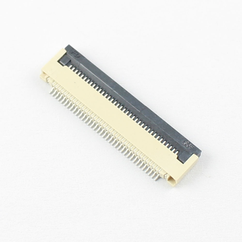
Connector Types
Connectors come in many types, each with specific pitch sizes. Common types include:
- Pin Headers – often 2.54 mm pitch, used in breadboards and development boards.
- Ribbon Cable Connectors – usually have a 1.27 mm pitch for compact wiring.
- Board-to-Board Connectors – pitch varies from 0.5 mm to 2.0 mm depending on use.
- USB and HDMI Connectors – specific pitch designed for data and power transmission.
The pitch size influences the connector’s shape and application.
Impact On Compatibility
Pitch size directly affects connector compatibility. Connectors with different pitch sizes cannot mate properly.
Mismatched pitch can cause poor contact, signal loss, or short circuits. Designers must match pitch to the device’s layout precisely.
Choosing the right pitch ensures easy installation and long-term reliability. It also helps maintain proper spacing for heat dissipation and prevents mechanical stress.
Pitch In Pcbs
The pitch in PCBs refers to the distance between the centers of two adjacent pins or pads of electronic components. This measurement plays a crucial role in designing and assembling printed circuit boards. Understanding pitch helps ensure components fit properly and function as intended on the board.
Component Placement
Pitch directly affects how components are placed on a PCB. Smaller pitch sizes allow for higher component density, which means you can fit more parts into a smaller area. However, tight spacing demands greater precision during assembly to avoid solder bridges or misalignment.
When I worked on a project with a 0.5 mm pitch, the tiniest misplacement caused multiple shorts. This taught me that careful handling and accurate machinery calibration are essential for fine-pitch components. You should always check if your assembly process can handle the pitch before finalizing your design.
Signal Integrity
Pitch also influences signal integrity in your PCB design. Close pin spacing can increase the risk of crosstalk, where signals from adjacent lines interfere with each other. This interference can degrade the performance of high-speed circuits.
To maintain good signal quality, consider the pitch alongside trace width and spacing. Adjusting these factors helps minimize unwanted noise and ensures reliable communication between components. Have you noticed signal problems that vanished after tweaking your layout’s pitch and spacing?

Credit: www.anzer-usa.com
Pitch And Miniaturization
Pitch in electronic components means the distance between pins or leads. Smaller pitch allows more components in less space. This helps make devices smaller and lighter. Miniaturization depends heavily on reducing the pitch size. It leads to compact circuits and faster signal transmission.
Trends In Electronics
Manufacturers push for smaller pitch sizes every year. This enables thinner smartphones and smaller wearables. Industry moves towards micro and nano pitches under 0.5 mm. Surface-mount technology (SMT) grows popular due to fine pitch capability. High-density interconnects use tiny pitches to fit more functions.
Challenges And Solutions
Small pitch causes problems during manufacturing and testing. Pins close together increase the risk of short circuits. Soldering becomes difficult with fine pitch components. Inspection requires advanced optical and X-ray tools.
- Improved solder paste and stencil designs help accuracy.
- Automated optical inspection (AOI) detects defects fast.
- Advanced placement machines position parts precisely.
- New materials reduce electrical interference between pins.
Pitch Tolerance
Pitch tolerance is a crucial aspect in electronic components that defines the allowable variation in the spacing between pins or leads. This small difference can significantly affect how components fit on a circuit board, influencing both performance and reliability. Understanding pitch tolerance helps you ensure that your designs meet manufacturing capabilities and maintain electrical integrity.
Manufacturing Limits
Every manufacturing process has limits on how precisely it can maintain pitch dimensions. These limits depend on the technology used, such as surface-mount or through-hole techniques. If the pitch tolerance is too tight, it can increase production costs or lead to higher rejection rates.
Consider a situation where a PCB manufacturer specifies a pitch tolerance of ±0.1 mm. If your design demands a smaller tolerance, you might face delays or extra expenses. Knowing these limits helps you design components that are easier to produce without sacrificing quality.
Quality Control
Quality control measures ensure that pitch tolerance stays within acceptable boundaries during production. Automated optical inspection (AOI) systems often check the spacing between component leads to catch errors early. This reduces the risk of soldering defects and circuit failures.
You can improve quality by specifying realistic pitch tolerances based on your manufacturer’s capabilities. This proactive step minimizes rework and enhances product reliability. Have you ever experienced delays because a component didn’t fit right? Managing pitch tolerance effectively can prevent such headaches.
Choosing The Right Pitch
Choosing the right pitch in electronic components is more than just matching sizes. It directly impacts the performance, reliability, and manufacturing cost of your project. Understanding the key factors behind pitch selection can save you from costly redesigns and performance issues.
Application Considerations
Think about where and how your component will be used. If you’re designing a compact device like a smartphone, a smaller pitch allows for higher component density and saves space. However, in industrial or automotive electronics, a larger pitch might be better for durability and easier soldering.
Ask yourself: Will the device face vibration, heat, or moisture? Components with a wider pitch often handle harsh conditions better because they reduce the risk of short circuits and improve mechanical strength.
Also, consider the assembly process. Automated machines handle fine pitch components well, but if you’re hand soldering, larger pitch components reduce the chance of errors. Your choice should align with the production method and environment.
Cost Vs Performance
Smaller pitch components typically cost more due to the precision manufacturing required. They often demand advanced PCB fabrication techniques and specialized assembly equipment. This can increase overall project expenses.
On the other hand, components with a larger pitch are usually cheaper and easier to work with, but they take up more space and might limit your design flexibility. You need to balance the cost savings with the desired electrical performance and form factor.
Have you considered how much you’re willing to invest in performance versus budget constraints? Sometimes spending a bit more on a finer pitch can lead to a more reliable and compact product, saving money in the long run.
Credit: www.electronicsandyou.com
Frequently Asked Questions
What Does Pitch Mean In Electronic Components?
Pitch is the distance between centers of adjacent pins or leads in electronic parts. It defines spacing for mounting and connection on circuit boards.
Why Is Pitch Important In Electronic Design?
Pitch ensures proper alignment and connectivity of components on PCBs. It affects compatibility, assembly, and electrical performance in circuits.
How Is Pitch Measured In Electronic Parts?
Pitch is measured in millimeters or inches, commonly from center to center of pins or pads. Standard pitches include 0. 5mm, 1. 27mm, and 2. 54mm.
What Are Common Pitch Sizes For Ics?
Common IC pitch sizes are 0. 5mm, 0. 65mm, 0. 8mm, 1. 0mm, and 1. 27mm. Smaller pitches suit compact devices; larger pitches ease manual soldering.
Conclusion
Pitch is a key factor in electronic components design. It defines the distance between pins or leads. This distance affects how parts fit on a circuit board. Smaller pitch allows more components in less space. Larger pitch makes soldering easier and reduces errors.
Understanding pitch helps you choose the right parts. It also improves the quality of your circuits. Remember, pitch impacts both assembly and performance. Keep this in mind when working with electronics. It makes your projects smoother and more reliable.
Leave a Reply