Are you ready to take control of your projects like a pro? Building a PID controller might sound complex, but with just a few basic electronic components, you can create one yourself.
Imagine having the power to fine-tune systems for stability and precision, whether it’s a robot, a temperature system, or a motor. This guide will walk you through every step, making it simple and clear. By the end, you’ll not only understand how a PID controller works but also have your very own working model.
Let’s dive in and unlock the potential of your electronics skills!

Credit: medium.com
Pid Controller Basics
Understanding the basics of a PID controller is essential before building one. A PID controller helps control systems by adjusting outputs based on feedback. It keeps processes stable and accurate. This section explains what a PID controller is, its parts, and where it is used.
What Is A Pid Controller?
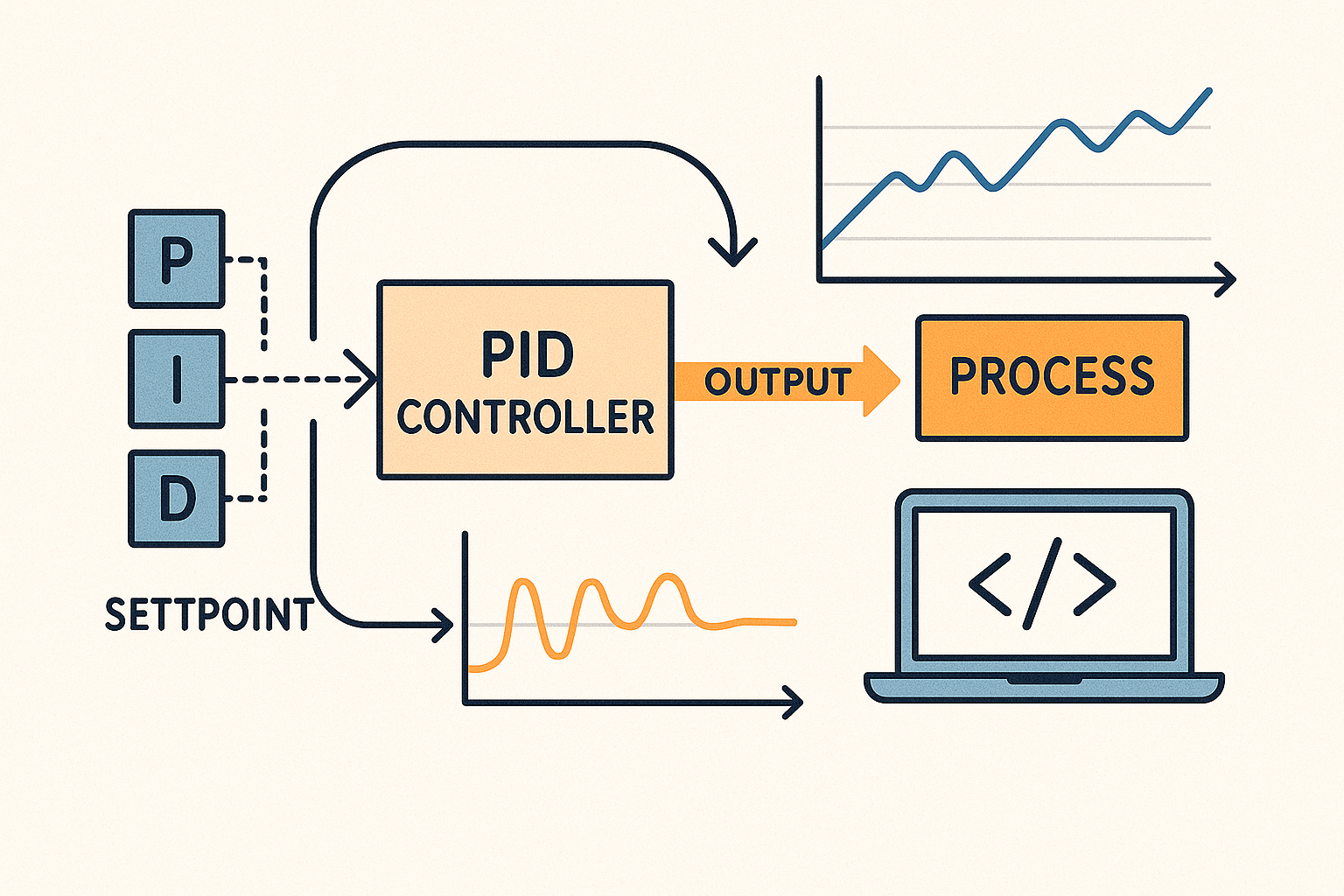
A PID controller is a control loop mechanism widely used in industrial control systems. PID stands for Proportional, Integral, and Derivative. These three elements work together to correct the error between a desired setpoint and a measured process variable. The controller calculates the difference and adjusts the output to minimize this error over time.
Components Of A Pid Controller
Every PID controller has three main components:
- Proportional (P):Reacts to the current error value. It produces an output proportional to the error.
- Integral (I):Focuses on the sum of past errors. It helps eliminate steady-state errors.
- Derivative (D):Predicts future errors by considering the error rate of change. It reduces overshoot and improves stability.
These components combine to provide a balanced and smooth control response.
Applications In Real Life
PID controllers are everywhere in daily life and industry. They regulate temperature in ovens and refrigerators. They control speed in electric motors and drones. They also manage pressure in water systems and flow in chemical plants. Their ability to maintain stability makes them vital in automation and robotics.
Credit: blog.zeptonow.com
Essential Electronic Components
Building a PID controller requires a set of basic electronic components. Each part plays a key role in controlling the system accurately. Understanding these components helps to design a simple yet effective controller. This section covers essential parts needed for the project.
Resistors And Capacitors
Resistors control the flow of electric current in the circuit. They set the gain and adjust signal levels. Capacitors store and release electrical energy. They help smooth signals and create timing functions. Together, resistors and capacitors shape the controller’s response.
Operational Amplifiers
Operational amplifiers, or op-amps, amplify small voltage signals. They perform mathematical operations like addition and integration. Op-amps are the heart of the PID controller circuit. They process error signals to generate control outputs.
Transistors And Diodes
Transistors act as switches or amplifiers in the circuit. They control the output current to the system. Diodes allow current to flow in one direction only. They protect the circuit and manage signal paths. Both components ensure reliable operation of the controller.
Assembling The Circuit
Assembling the PID controller circuit is where your design starts to come alive. This stage demands patience and precision. It’s your chance to turn theory into a tangible, working system that you can test and tweak.
Designing The Circuit Layout
Begin by sketching the circuit layout on paper or using simple software. Arrange components logically to minimize wire crossing and reduce noise interference. Keep power lines and signal lines separated to avoid unwanted feedback.
Think about component placement for easy access during testing. For instance, place potentiometers or variable resistors where you can easily adjust them without dismantling the board. Planning ahead here saves you hours later.
Wiring And Soldering Tips
Use solid-core wires for breadboards and stranded wires for permanent connections. Always strip wires neatly to ensure strong connections. Avoid excessive solder as it can create shorts or cold joints.
Hold the components firmly while soldering to prevent movement and cold joints. Check each joint visually; it should look shiny and smooth. If you have a multimeter, test the connections for continuity before powering the circuit.
Testing The Circuit
Start testing with the power off. Double-check wiring against your schematic to catch any mistakes. Then, power the circuit and watch for any unusual signs like overheating or smoke.
Use a multimeter to measure voltages at key points to ensure they match expected values. Adjust your PID parameters carefully, and observe how the output changes. What happens if you tweak the proportional gain first? How does the system respond? This hands-on exploration helps you understand the controller’s behavior deeply.
Tuning The Pid Controller
Tuning a PID controller is where your project really starts to come alive. This process adjusts the proportional, integral, and derivative settings to make your controller respond just right. Without proper tuning, your system could be sluggish, unstable, or constantly overshooting the target.
Understanding Pid Parameters
Each PID parameter plays a distinct role in controlling your system’s behavior.
- Proportional (P):This controls the reaction to the current error. Increasing P makes the system respond faster but can cause overshoot.
- Integral (I):This accounts for past errors and helps eliminate steady-state errors over time.
- Derivative (D):This predicts future errors based on the rate of change, helping to reduce overshoot and improve stability.
Getting the balance right between these parameters is key. Think of P as the immediate response, I as the memory, and D as the foresight of your controller.
Methods For Tuning
You don’t need fancy equipment to tune your PID controller. Basic trial and error can work well if you know what to look for.
- Start by setting I and D to zero. Increase P until the system oscillates steadily.
- Next, slowly add I to remove any steady-state error but watch out for slow oscillations.
- Finally, add D to dampen oscillations and improve stability.
Another approach is the Ziegler-Nichols method, which uses the oscillation period and critical gain to calculate PID values. It’s practical when you want a structured starting point.
Common Tuning Mistakes
Many beginners rush through tuning without fully understanding each parameter’s impact.
- Setting the integral too high can cause the system to wind up and overshoot repeatedly.
- Too much derivative action can make the controller overly sensitive to noise.
- Ignoring system response time often leads to unstable tuning.
Have you noticed your system swinging wildly after tweaking one parameter? That’s a sign you may have pushed it too far without balancing the others. Patience and small incremental changes are your best allies during tuning.
Troubleshooting Common Issues
Troubleshooting is a crucial part of building your PID controller with basic electronic components. It helps you pinpoint problems quickly and get your circuit running smoothly. Understanding common issues and how to fix them saves you time and frustration.
Identifying Faulty Components
Start by checking each component visually for any damage like burn marks or broken leads. Use a multimeter to test resistors, capacitors, and transistors for correct values and continuity.
Sometimes, a tiny crack in a capacitor can cause the entire circuit to behave erratically. Have you ever swapped a resistor only to find the problem disappeared? That’s a clear sign the component was faulty.
Also, ensure your power supply is stable and delivering the right voltage. Fluctuations here often mimic component failure but are easier to fix.
Debugging The Circuit
Trace your circuit step-by-step to ensure signals flow as expected. Use an oscilloscope or a simple LED to check if the PID controller’s output changes with input variations.
Pay attention to wiring mistakes or loose connections. Even a single misplaced jumper wire can cause the controller to malfunction.
If your output is stuck or oscillating wildly, try isolating sections of the circuit. Testing smaller parts separately can reveal exactly where the issue lies.
Improving Performance
If your PID controller feels sluggish or too jumpy, tweaking your component values might help. Adjust the proportional, integral, and derivative gains carefully and observe the response.
Adding small capacitors to filter noise can stabilize the output without changing your core design. Have you considered adding a heat sink or better grounding to reduce interference?
Remember, performance tuning is an iterative process. Keep notes on each change so you can track what improves your controller and what doesn’t.
Advanced Modifications
Advanced modifications let you improve your PID controller’s performance. These changes go beyond basic setups. They help handle complex systems and improve control accuracy. Such upgrades bring flexibility and robustness to your design.
Adding Feedback Loops
Feedback loops monitor the output and adjust the input automatically. This helps the system correct errors faster. You can add sensors to measure output values continuously. The sensor data feeds back into the controller for real-time adjustments.
Use operational amplifiers or comparators to create these loops. This setup improves response time and reduces steady-state error. Feedback loops make the PID controller more precise and reliable.
Integrating With Microcontrollers
Microcontrollers add smart control to your PID system. They process sensor inputs and calculate control signals quickly. Use Arduino, PIC, or Raspberry Pi boards for integration.
Programming the PID algorithm on a microcontroller allows easy tuning. You can change parameters without rewiring circuits. It also enables data logging and remote control features.
This integration brings flexibility and automation to your project. It adapts the controller to different tasks with simple code updates.
Enhancing Stability
Stability is vital for smooth and safe system operation. You can enhance it by adjusting PID gains carefully. Use techniques like Ziegler-Nichols tuning or trial and error.
Adding low-pass filters can reduce noise and prevent oscillations. Use capacitors or dedicated filter circuits in the feedback path.
Implementing anti-windup mechanisms prevents the integral term from causing instability. These steps ensure your PID controller works steadily under all conditions.

Credit: www.youtube.com
Frequently Asked Questions
What Basic Components Are Needed For A Pid Controller?
You need resistors, capacitors, operational amplifiers, and a power supply. These components form the proportional, integral, and derivative parts of the PID controller. Basic tools like a breadboard and multimeter are also essential for assembly and testing.
How Does A Pid Controller Improve System Performance?
A PID controller continuously adjusts output based on error values. It reduces overshoot, steady-state error, and improves stability. By tuning proportional, integral, and derivative gains, it optimizes the response time and accuracy of control systems.
Can I Build A Pid Controller Without Microcontrollers?
Yes, a PID controller can be built using analog components only. Operational amplifiers and passive components create the proportional, integral, and derivative functions. This approach is useful for simple, low-cost, or real-time control applications without programming.
How To Tune Pid Parameters Using Basic Electronics?
Start with proportional gain to reduce error, then add integral to eliminate steady-state error. Finally, adjust derivative gain to minimize overshoot. Use trial and error or Ziegler-Nichols methods while monitoring system response for optimal tuning.
Conclusion
Building a PID controller with basic parts is simple and rewarding. You control how machines react and adjust. This guide showed easy steps anyone can follow. Practice helps you understand each part’s role better. Keep experimenting to improve your control skills.
Soon, you will create more precise and stable systems. Start with small projects and grow your knowledge. Control your world with simple electronics.
Leave a Reply