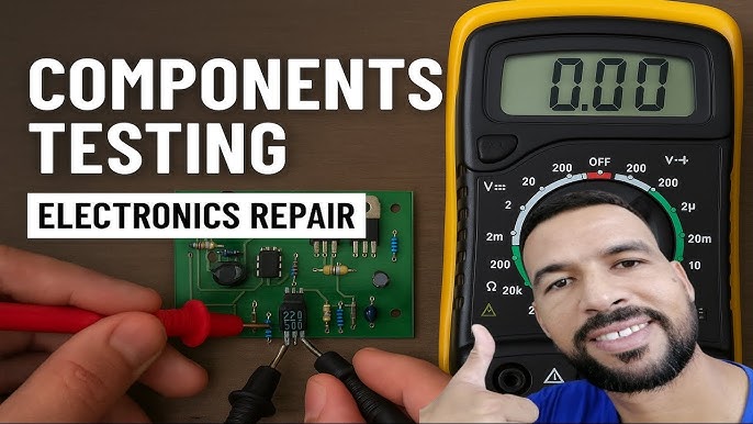
Are you tired of guessing whether your electronic components are working or not? Imagine saving time and money by quickly finding out if a resistor, capacitor, or diode is faulty—all by using a simple tool you probably already have: a digital multimeter.
You will learn easy, step-by-step methods to check your electronic components with confidence. Whether you’re fixing a gadget or building a new project, mastering this skill will make your work faster and more accurate. Keep reading, and you’ll discover how to make your digital multimeter your most trusted assistant.
Digital Multimeter Basics
Understanding the basics of a digital multimeter can transform how you troubleshoot electronic components. A digital multimeter (DMM) is an invaluable tool for anyone working with electronics. Whether you’re a hobbyist or a professional, mastering its use can save you time and frustration.
Types And Features
Digital multimeters come in a variety of types, each with its own set of features. Some are designed for simple household tasks, while others are built for complex industrial projects. Choosing the right type depends on your specific needs.
- Basic Multimeters:Ideal for household use, offering essential functions like measuring voltage, current, and resistance.
- Advanced Multimeters:Equipped with additional features like capacitance measurement, frequency counter, and temperature readings.
- Auto-Ranging Multimeters:Automatically selects the correct range for measurement, making them user-friendly.
Consider what features matter most to you before making a purchase. An auto-ranging multimeter might be ideal if you’re new to electronics.
Key Functions To Know
Familiarizing yourself with the key functions of a digital multimeter is crucial. It’s not just about turning it on and hoping for the best. Knowing what each setting does will help you get accurate readings.
- Voltage Measurement:Essential for checking power supplies and battery levels. Ensure the probes are connected correctly to prevent damage.
- Current Measurement:Useful for identifying power consumption and ensuring circuits aren’t overloaded.
- Resistance Measurement:Helps in testing continuity and detecting faults in components.
Have you ever wondered why your circuit isn’t working despite everything looking fine? Often, it’s a simple resistance issue that a quick check with your multimeter can resolve.
Understanding these basics can make all the difference in your electronics projects. So, what will you check first with your digital multimeter?
Credit: circuitdigest.com
Preparing For Testing
Preparing for testing electronic components with a digital multimeter is crucial. It ensures accurate readings and protects both you and the device. This stage sets the foundation for effective troubleshooting and measurement.
Safety Precautions
Safety is the top priority before starting any electrical test. Always work in a dry area to avoid electric shock. Use insulated tools and wear protective gear like gloves and goggles. Double-check that the circuit is powered off or disconnected. Handle components carefully to prevent damage. Keep your workspace clean and organized to reduce risks.
Setting Up The Multimeter
Begin by turning on the multimeter and checking its battery level. Select the correct measurement mode based on the component type. For example, use resistance mode for resistors and diode mode for diodes. Connect the test leads firmly to the multimeter ports. Calibrate the device if needed, following the user manual. Confirm that the probes are clean and in good condition for precise results.
Testing Resistors
Testing resistors is a basic skill for anyone working with electronics. Resistors control the flow of electric current in circuits. Checking their values ensures devices work correctly. A digital multimeter helps measure the resistance quickly and accurately. Understanding the readings helps find faulty or damaged resistors.
Measuring Resistance
Set the multimeter to the resistance mode, often marked as Ω. Disconnect the resistor from the circuit to avoid false readings. Connect the multimeter probes to each end of the resistor. Hold the probes steadily to get a stable reading. The display shows the resistance value in ohms (Ω). For very small or large resistors, the unit may change to kilo-ohms (kΩ) or mega-ohms (MΩ).
Interpreting Results
Compare the measured value with the resistor’s color code or labeled value. A small difference is normal due to tolerance. Tolerance shows how much the resistor value can vary. If the reading is far off or shows infinite resistance, the resistor may be broken. Very low or zero resistance could mean the resistor is shorted. Replace any resistor that does not match its expected range.

Credit: www.youtube.com
Checking Capacitors
Checking capacitors is essential when testing electronic components. Capacitors store electrical energy and affect circuit performance. Faulty capacitors can cause devices to fail or behave unpredictably. A digital multimeter helps measure their capacitance and identify problems. It provides quick and accurate readings to ensure capacitors work well.
Capacitance Measurement
Set the multimeter to the capacitance mode, usually marked with “F” or a capacitor symbol. Connect the multimeter probes to the capacitor terminals. Observe the reading on the display. Compare the measured value to the capacitor’s rated value printed on its body.
Keep these tips in mind:
- Discharge the capacitor fully before testing.
- Remove the capacitor from the circuit for accurate results.
- Use the correct range on the multimeter if it is not auto-ranging.
Capacitance readings close to the rated value indicate a good capacitor. Large deviations show possible damage or aging.
Detecting Faulty Capacitors
Look for signs of failure such as bulging, leaking, or discoloration on the capacitor. Use the multimeter to check resistance by switching to ohms mode. Connect the probes to the capacitor terminals.
Healthy capacitors show a changing resistance value as they charge. A constant low or high resistance suggests a short or open circuit inside the capacitor.
- A short circuit will show near zero resistance.
- An open circuit will show infinite or very high resistance.
Testing for leakage current or ESR requires specialized tools but basic multimeter checks help find many faulty capacitors.
Testing Diodes
Testing diodes with a digital multimeter is a straightforward way to check if they’re functioning properly. Diodes allow current to flow in one direction, and your multimeter can help you verify this behavior by measuring resistance or voltage drop. Understanding how to read these measurements will save you time and prevent guesswork in your electronic projects.
Forward And Reverse Bias Tests
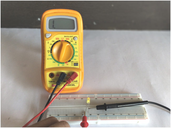
To test a diode, set your multimeter to the diode test mode. Connect the red probe to the anode and the black probe to the cathode to perform the forward bias test. A healthy diode typically shows a voltage drop between 0.5V and 0.8V, indicating it’s allowing current to flow.
Reverse the probes for the reverse bias test—red probe to cathode and black to anode. The multimeter should show no reading or “OL” (open loop), meaning the diode blocks current in this direction. If you see a voltage drop here, the diode may be faulty.
Identifying Shorted Or Open Diodes
If the diode shows a very low voltage drop or close to zero in both forward and reverse tests, it’s likely shorted, allowing current to flow both ways. This can cause circuit failures and unexpected behavior.
On the other hand, if the multimeter shows “OL” or no reading in both directions, the diode is open and not conducting at all. This means it’s broken and needs replacement.
Have you ever spent hours troubleshooting only to find a single faulty diode? Testing these components early can prevent such frustrating scenarios.
Checking Transistors
Checking transistors with a digital multimeter is a straightforward way to identify if your transistor is functioning properly or if it needs replacement. Transistors, being crucial components in circuits, control current flow and amplify signals. Knowing how to test them yourself saves time and avoids guesswork in troubleshooting electronics.
Using The Diode Test Mode
The diode test mode on your digital multimeter lets you check the junctions inside a transistor just like you would with a diode. This mode provides a small voltage, allowing you to see the forward voltage drop across transistor junctions.
Start by setting your multimeter to diode test. Then, place the positive lead on the transistor’s base and the negative lead on the emitter. You should see a reading between 0.6V and 0.7V if the junction is good.
Reverse the leads to check for no conduction, indicating a healthy junction. Repeat the same process between the base and collector. If you get readings outside these ranges or see conduction both ways, the transistor might be faulty.
Verifying Npn And Pnp Types
Identifying whether your transistor is NPN or PNP is crucial before testing. You can do this easily with your multimeter’s diode test mode by observing how the leads interact with the transistor terminals.
- NPN Transistors:The positive lead on the base and the negative lead on the emitter or collector should show a forward voltage drop. Reverse leads should show no conduction.
- PNP Transistors:The negative lead on the base and the positive lead on the emitter or collector should show a forward voltage drop. Reversing leads should give no conduction.
This simple check helps you confirm transistor type and also quickly spot damaged components. Have you ever tried this and found a transistor that looked fine but tested faulty? It’s a reminder that visual inspection isn’t enough.
Measuring Inductors
Measuring inductors with a digital multimeter helps verify their condition. Inductors store energy in a magnetic field when current flows through them. Checking their resistance and continuity ensures they work properly. Detecting coil damage prevents circuit failures and improves device performance.
Resistance And Continuity Checks
Set the multimeter to the resistance (ohms) mode. Connect the probes to the inductor terminals. A good inductor shows low resistance, usually close to zero ohms. High resistance or infinite reading means the coil may be broken.
Switch to continuity mode to hear a beep if the coil is intact. No beep indicates a broken coil or open circuit. Always test the inductor out of the circuit for accurate results.
Detecting Coil Damage
Coil damage can cause shorts or open circuits inside the inductor. Use the multimeter to check for unusual resistance values. Compare readings with the manufacturer’s specifications. Visual inspection helps spot burns or physical damage on the coil.
Tap the inductor gently while measuring resistance. Fluctuating readings hint at loose or broken wire inside. Replace any damaged inductors to maintain circuit reliability and safety.
Testing Continuity And Wires
Testing continuity and wires is a fundamental skill when working with electronic components. It helps you quickly find out if a wire or connection is complete without any breaks. With a digital multimeter, you can easily check these connections to avoid troubleshooting frustrations later.
Continuity Mode Usage
Set your digital multimeter to the continuity mode, usually indicated by a sound wave or diode symbol. Touch the two probes together first to ensure the meter beeps, confirming it’s ready. Then, place the probes on either end of the wire or component you want to test.
If the meter beeps, the connection is continuous, meaning electricity can flow through without interruption. No beep means there’s a break somewhere, and the wire or connection is faulty. This quick feedback saves you time and guesswork during repairs.
Finding Broken Connections
Imagine you have a long wire harness, and a device isn’t working. Instead of replacing the whole thing, use the continuity test to pinpoint the exact break. Move the probes along the wire at different points, listening for the beep.
When the beep stops, you’ve found the break. Mark the spot and inspect it closely—sometimes the wire is visibly damaged or the solder joint is loose. This targeted approach keeps your repairs efficient and cost-effective.
Common Troubleshooting Tips
Checking electronic components with a digital multimeter can sometimes lead to confusing results. Common troubleshooting tips help you avoid frustration and get accurate readings faster. Understanding these tips can save you time and prevent damage to your components or your multimeter.
Avoiding Measurement Errors
One common mistake is not setting the multimeter to the correct mode. Always double-check if you’re measuring voltage, resistance, or current before connecting the probes.
Ensure the probes have a solid connection with the component leads. Loose contact can cause fluctuating or incorrect readings.
Remember to discharge capacitors before testing. A charged capacitor can give false resistance or continuity values and even damage your multimeter.
Have you ever been confused by a reading that just doesn’t make sense? Check for interference from nearby electronic devices or strong magnetic fields, which can distort your measurements.
Maintaining The Multimeter
Regularly inspect your multimeter and probes for wear and tear. Cracked insulation or bent probes can lead to inaccurate results or pose safety risks.
Replace batteries promptly. A low battery often causes weak backlight or inaccurate readings, which can mislead your troubleshooting efforts.
Store your multimeter in a dry, dust-free environment. Moisture and dirt can damage internal components and shorten the device’s lifespan.
Have you cleaned your multimeter recently? Keeping the contacts and rotary dial clean ensures smoother operation and better reliability.

Credit: www.youtube.com
Frequently Asked Questions
How Do I Test Resistors With A Digital Multimeter?
Set the multimeter to the resistance mode (Ω). Connect probes to resistor leads. Read the displayed value and compare it to the resistor’s rated value. A close match confirms the resistor is functional.
Can I Check Capacitors Using A Digital Multimeter?
Yes, but only with a multimeter that supports capacitance testing. Set it to the capacitance mode, connect the probes to capacitor terminals, and observe the reading. A value close to the rated capacitance indicates a good capacitor.
How To Measure Diode Functionality With A Digital Multimeter?
Set the multimeter to diode mode. Place the red probe on the anode and black on the cathode. A forward voltage drop around 0. 6-0. 7V indicates a good diode. Reverse the probes; it should show no conduction.
What Is The Correct Multimeter Setting For Testing Transistors?
Use the diode test mode to check transistor junctions. Test between base-emitter and base-collector terminals. Proper junctions show a voltage drop, while open or short readings indicate a faulty transistor.
Conclusion
Checking electronic components with a digital multimeter is simple and useful. You can test resistors, capacitors, and diodes quickly. Always follow safety steps to avoid damage or injury. Practice helps you gain confidence and accuracy. This skill saves time and money on repairs.
Start with basic tests and build your knowledge slowly. Remember, careful measurement gives clear results. Keep your multimeter ready for any electronics work. This way, you understand your devices better and fix problems faster.
Leave a Reply